The SuperSensor: Your all-in-one Home Assistant satellite
My own take on the multi-function Home Assistant sensor and voice hub
DIY, Home Automation
Table of Contents
The Motivations
I’ve been interested in voice-based home automation for many years now; in fact, it was one of the first posts on this blog. For many years I now I’ve used it to control the lights in my bedroom, for two major reasons: first, the lights I was using were not hardwired, and I had many of them, and thus many little switches on cords; second, I wanted to be able to switch things on and off from wherever I was - be it my bed, my couch, or just outside the room as I was leaving - without having to fiddle with all those switches.
So I went with Home Assistant, then and now the de facto FLOSS standard for home automation. I bought a few smart plugs, from various manufacturers throughout the years (currently settled very nicely on Athom ESPHome-based ones). And I set up Kalliope on a Raspberry Pi to do it. And it did work wonderfully for a very long time, with some fits and starts at times.
In the middle of 2023 though, I wanted to expand things a bit. Over the years I had added more smart switches in two other main zones: my garage, where they control an infrared heater, several fans, and several lights; and in my basement, where they control again several fans and lights. So I went looking to buy a few more ReSpeakers and Raspberry Pi’s to build out a few more voice control nodes.
But I ran into two major problems. First, the original ReSpeaker units I was using had been discontinued, and while there was a nice replacement fit for a Raspberry Pi Mini, these were quite expensive. And second, coming out of the pandemic, Raspberry Pi availability has been basically nonexistent. I specifically wanted the aforementioned Mini units, the Mini 2 W to be precise, and on the one occasion in all of 2023 that I could get one (in October, several months after I started this project!), I could only get one. It seemed my plans had to wait…
But then I checked the Home Assistant blog and boy was I in for a treat!
The Year of the Voice
The Home Assistant project dubbed 2023 “The Year of the Voice”. Their goal was to make voice control the primary focus of their development efforts for the year, and by June 2023 they had made excellent progress, landing one of the most critical features: wake word support. I was immediately intrigued and set about trying to set up an ESP32-based satellite device for Home Assistant. Later in 2023, the support got even better. There’s still some flaws - at least, I think they’re flaws, though others in the project and community disagree - but it works pretty damn well with a bit of tweaking and hackery.
After some experimenting, I had a working prototype streaming voice to my Home Assistant instance. And then I got an idea.
I had recently seen a Reddit post about the Everything Presence One, and I thought, why not try making my own, but combining it with this voice control aspect? Thus, the idea for the SuperSensor was born.
Part One: Finding The Parts
Based on the EP1, I wanted the SuperSensor to have the following parts:
-
A microphone. This is pretty much a given for the voice control portion, but I had to find a good option. Luckily support for the INMP441 MEMS microphone is pretty good in ESPHome, and these are what I had used in my tests, so it seemed like the most obvious solution. Amazon search link, since the vendors change fast and both of my orders were different from each other and from the currently available stock. About $3.00 CAD each.
-
LEDs for visual feedback. I’m not a big fan of voice systems that “talk back”, and I really liked the ReSpeaker’s LED-based feedback mechanism. So I wanted to use LEDs for that purpose here. After a few prototypes, I settled on a design with two RGB common-cathode LEDs which could be driven directly from the GPIOs of the ESP32. Initially I tried using a transistor power delivery system, but due to some missing knowledge on my part and having the wrong kind of transistor, they didn’t work, and I found that the ESP’s GPIO pins could easily drive both LEDs without issue, so I just went with that. Amazon search link, same situation as the INMP441’s. About $0.14 CAD each. I also added a ~300Ω resistor to limit current, though I had these lying around so add ~$0.10 CAD to buy these.
-
A radar sensor. Millimetre-wave radar is absolutely critical for a presence sensor like this, because it allows continuous tracking without motion. I tried 5 different models, but settled on the HLK LD2510C, since it had the best combination of features, configurability, and ESPHome support. AliExpress link though ensure you select the “LD2410C-P” out of the options. About $5.27 CAD each (including shipping).
-
A PIR sensor. PIR comes in very handy for detecting quick motion, and as a backup (in both directions) for the Radar for initial presence detection. I tried a few options but the SR602 ended up being both the cheapest, nicest form factor, and best performing of the various options I tried. AliExpress link but I did replace the Fresnel cover with a cover from a different sensor that looked nicer and seemed to perform a little better, because I had them from my testing. About $2.37 CAD each, plus $0.90 CAD each for 10 of the alternates for their covers (including shipping).
-
A light sensor. While the LD2410C does have “light detection” capabilities, it doesn’t actually expose this in a useful way. I wanted a separate light sensor for two main reasons: first, it allows more granular control (e.g. trigger only with presence + lights) for things that are not themselves lights, or for lights in a room with natural light; and second, it can be useful to know how bright the room is for other automations. I originally went with the VEML7700 sensor, but at the time its ESPHome support was subpar, requiring an external custom module that was deprecated. While it is a bit more pricey, I wanted a reliable unit with good ESPHome support, so I went instead with the TSL2591 for the final version. One upside here is that it is able to track infrared light separately from visible light, and though I haven’t found an actual use for this yet myself, it might come in handy for someone. AliExpress link. About $6.02 CAD each (including shipping).
-
A temperature sensor. I looked at, and ended up buying, a few different options here, all based on the standard Bosch BM sensors: the BMP280, BME280, and the BME680. The first was an error, as I definitely wanted the humidity option as well, so I purchased several BME280’s, before finally deciding that the VOC/air quality detection of the BME680 was worth it. AliExpress link. About $6.81 CAD each (including shipping).
-
An ESP32. I also went through several different ESP units before deciding on a particular one with a slim profile and integrated antenna trace, as this made the sensor more compact, and had a USB-C connector for better mechanical and electrical support. AliExpress link though ensure you select the “HW-395” out of the options. About $10.18 CAD each (including shipping).
The last piece was some female pin receptors to hold the ESP32 boards. I did this to allow a quick swap-out should that ever be needed, and these cost about $15.99 CAD for 10 40-pin strips (Amazon link), with each sensor using one strip, or about $1.60 CAD each.
All together, to build one sensor the non-board parts cost about $36.39 CAD including shipping from AliExpress (but not Amazon, because I have Prime). While I could probably improve on some of the parts, I felt this was a good balance and in practice this combination does work quite well with no complaints across 6 sensors.
Part Two: Designing a Board
Of course, just stringing the parts together wouldn’t look very nice or fit very well on a wall, so I designed a custom PCB to integrate all the components using the EasyEDA online builder. I went through two prototype designs before settling on a final design that I’m quite happy with. This design sits in a horizontal orientation with the power cord exiting the right side (when facing the unit), which suited all my planned installation points nicely. This could also be used as a guide to create a vertical or flipped horizontal orientation should one so choose. The design is open source (GPLv3 along with the following ESPHome code) and is available in the Git repository in both DXF and EasyEDA JSON formats. Note that all pictures are of my second prototype and the final design does fix a few flaws I had with it such as removing some unneeded transistor points, dropping the second LED resistor, and improving a couple trace paths.
The final result with black silkscreening looks fantastic to me, and I love the way the different colours of the individual components are highlighted, as well as hiding the ESP32 behind the unit. In fact, I liked this appearance so much that I abandoned my original plan of designing a 3D-printed case for them, in favour of the bare board. While this might not suit everyone, I like the “DIY PCB” look in my home, and building a case shouldn’t be too hard based on the board dimensions.
I was able to order 10 boards for $23.05 CAD shipped, or $2.31 each, bringing the parts total for each SuperSensor to $38.70.
Assembly was a bit more work, having to solder the various sensors and pin strips to the boards, and took about 30 minutes per sensor once I got going. The result was a sleek unit that could be placed fairly inconspicuously in corners of rooms, and I then used extra-long USB3 cables and stainless steel strapping to hold them up, for a definite DIY look.
Part Three: The ESPHome Configuration
Lastly, I had to write the ESPHome configuration to make everything work. Mostly, this just involved exposing the individual sensor components, but as I built it I wanted to make this more universal. To that end, I added several configuration options and a full “presence” system.
The voice component is pretty straightforward to get working with the sensor, and as long as you have a Home Assistant Assist pipeline working with a speech-to-text and wake word engine going, it should be plug-and-play.
You can select how long a PIR detection is “held” for. This is needed since, unlike most DIY PIR sensors, the SR602 as a fixed ~3 second hold time. This wasn’t long enough for me in some situations, so I added a latch timer to output a second template sensor value based on the PIR and the hold time: as long as the sensor fires or continues firing within this time, the result sensor remains active; once the timer expires with no further PIR detection, it will become inactive. Thus you could set the PIR detection between 0 (~3) and 60 seconds, with a default of 15 seconds, a good value for most uses.
You can control at what threshold light level “presence” is detected. This is useful to configure the light presence option below based on the actual conditions of the room, the light that falls on the sensor, etc. You can set this anywhere between 0 (always on) and 200 lux, in 5 lux increments, with a default of 30 lux (a decent brightness from a room light).
You can disable voice control. This basically defeats the purpose of my design over something like the EP1, but could be useful in some cases (having multiple sensors in one room for example).
Finally, the big feature: a multi-factor presence detection system. Each major sensor - PIR, Radar, and Light - outputs, based on the above options, an overall “presence” detection sensor. You can select an option both for inbound presence and outbound (cleared) presence, as to what sensors are used to create an overall presence sensor which could then be used in automations.
I go through all the options in the README of the Git repository linked above, but I wanted to highlight the two configurations that I’ve been using to great success.
Inbound PIR + Radar + Light, Outbound Radar + Light
I use this configuration for my garage heater. Obviously, a heater turning on when no one is present is both a waste of energy, and a potential fire hazard, so this was the original motivation for making this configurable: I wanted something extremely safe that would definitely only trigger when someone was actually there. This option combines all 3 sensors on the inbound, meaning that someone must first turn on the light (light level), walk in front of the sensor (PIR), and finally, to avoid PIR false triggers, trigger the Radar sensor. On the outbound, either the light being turned off (light level) or the Radar no longer detecting will turn off presence, and thus, the heater. So far this has worked flawlessly in both directions.
Inbound PIR + Radar, Outbound Radar
This is the configuration I use for most of my other sensors, i.e. any that trigger lights on or off. The logic is fairly simple: both PIR and Radar must detect presence for the lights to turn on, preventing false-positives, while only the Radar is required to maintain presence.
Part Four: The Pictures
What would a DIY post be without pictures? Here’s a few!
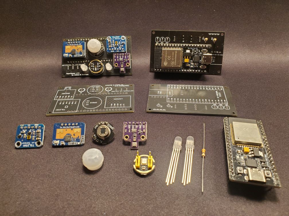
Here’s an overall shot showing both a completed unit and the breakout of all the parts.
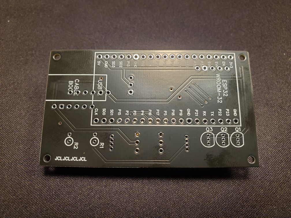
Here is the blank PCB, from both the front and back. As mentioned above this is a prototype board, so while there are some differences from the final PCB, the overall layout is correct.

As part of testing all the sensors, I made a socketed version. While this makes the unit extremely thick, it might be a good idea to build one of these to test all your sensors before proceeding with the meticulous soldering of all the components to the boards, because de-soldering them later is basically impossible (godspeed to the BME680 sensor that did not make it).
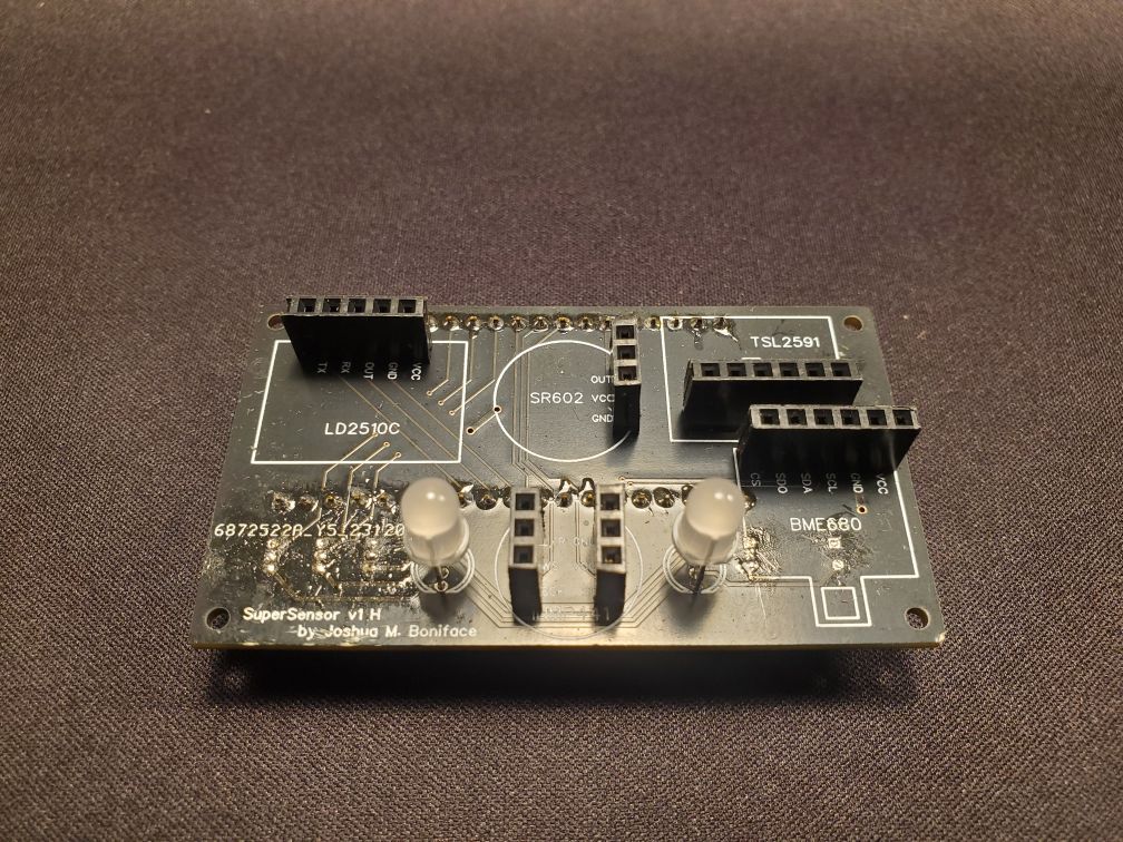
Here is a completed board, from the front, back, back without the ESP32 installed, and short side. The ESP32 is socketed on the final boards, both to provide good airflow and to allow quick swapping of the “brains” of individual units if needed, but all the sensors are soldered directly to the board to keep the profile low.


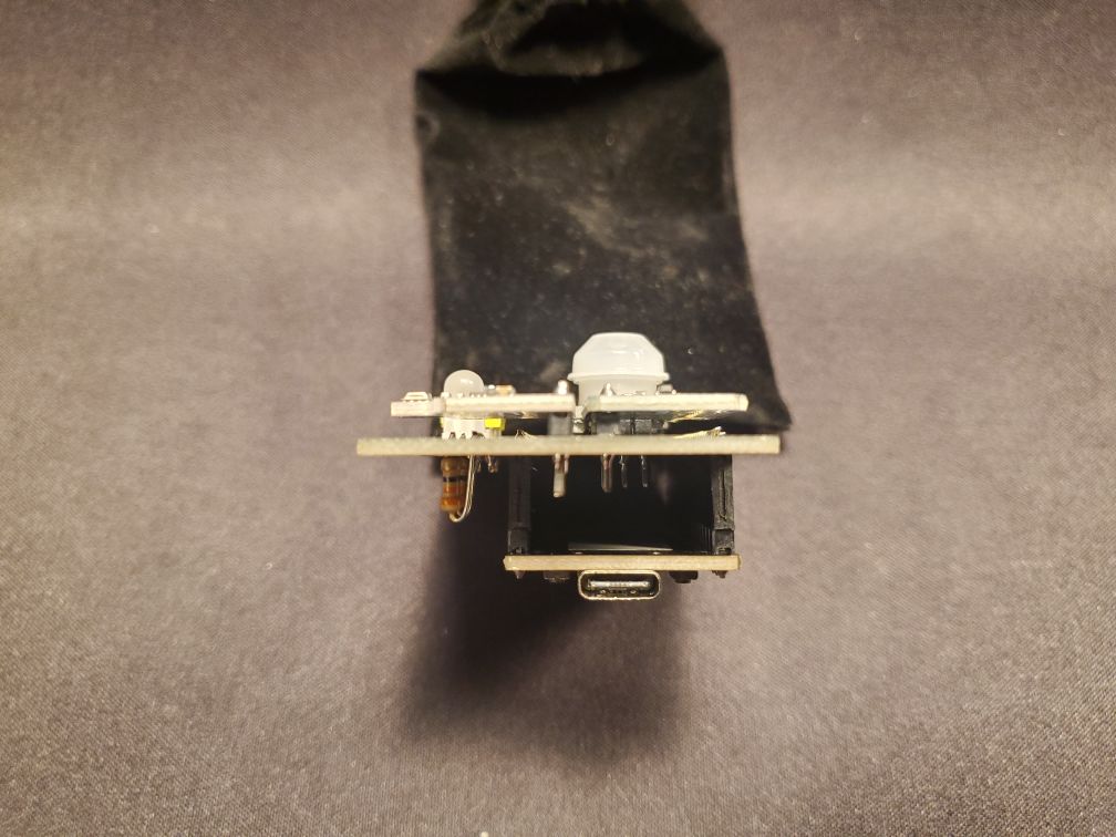
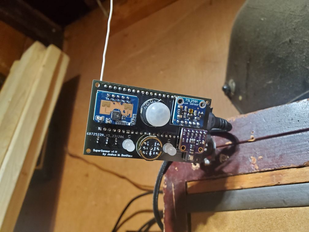
Here is one of the boards in its final mounted location, angled to provide perfect coverage of my garage. Due to where it sits, I had to bodge a makeshift antenna extension onto this one to get a decent WiFi connection, but it works well and this hasn’t been needed for any of my other ones.
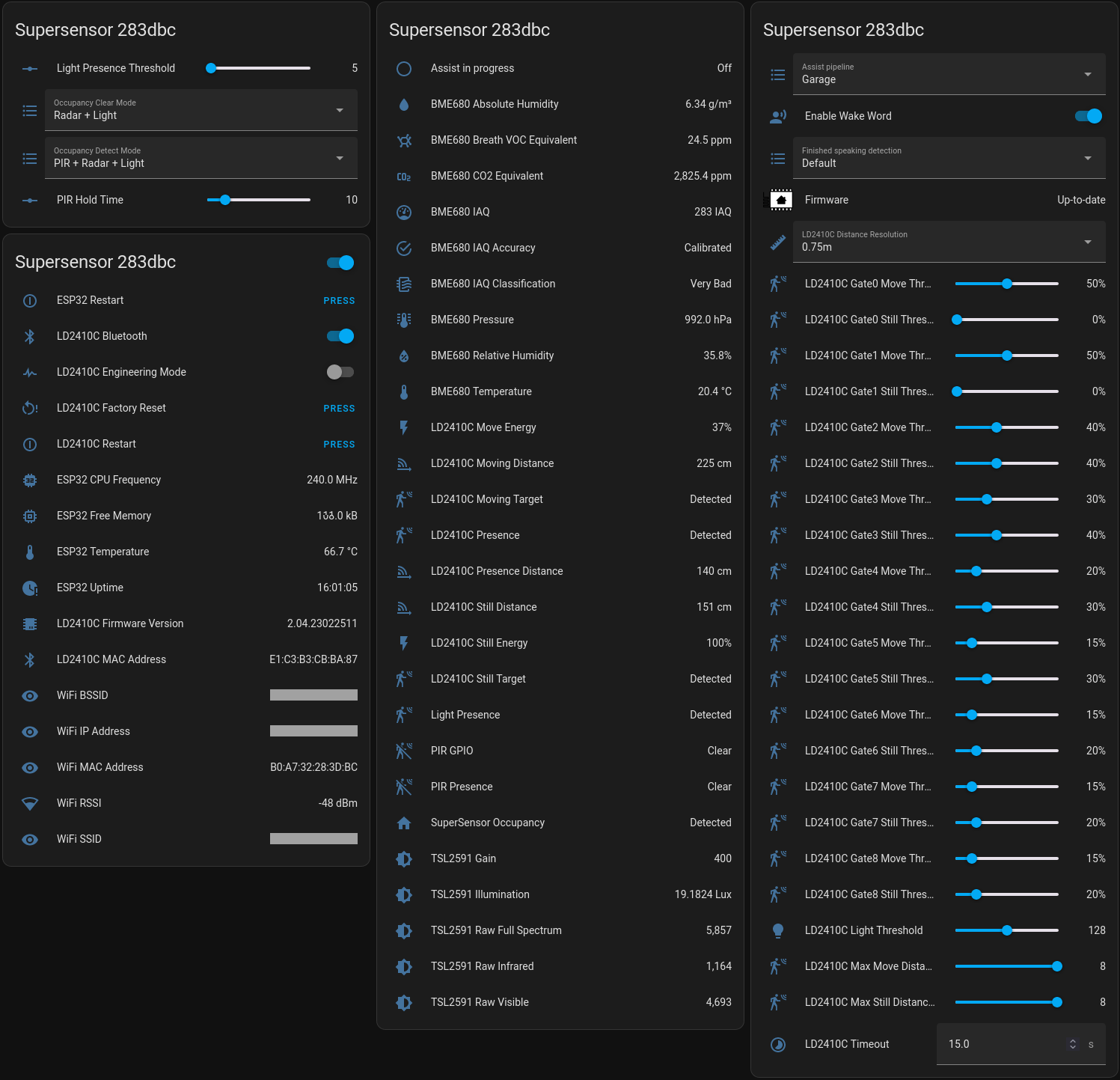
Here is all the information and configuration the SuperSensor provides in Home Assistant.
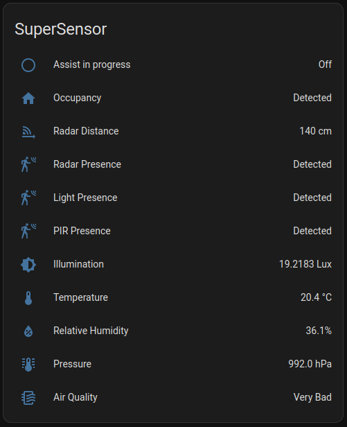
That is quite a lot of information, so in my actual dashboards I usually only show the most relevant parts for that particular use-case, like this one for my garage sensor.
Finally, here is a video demonstration of the voice control in action. This shows the LED feedback colours for listening (blue), processing (cyan), and both positive (green) and negative (red) responses in lieu of a voice response.
Final Thoughts
All in all, I’m very happy with how the SuperSensor turned out. I’m currently using 5 of them in my house (one in my garage, one in my bedroom, and three in my basement), with another 5 either partially- or fully-built and ready to go when I find locations for them (my outside gazebo seating area being an obvious next choice when the weather improves).
As mentioned above, I’ve open sourced both the PCB design and the ESPHome configuration under the GNU GPLv3, as well as provided the full parts list with links, so if this design interests you, you can build one (or several, minimum PCB orders and all) yourself for under $40.00 CAD.
I’ve also ensured that the ESPHome configuration is properly packaged: you can flash a SuperSensor via USB (esphome run supersensor.yaml from the repository), then it behaves like most ESPHome-based products: you connect to the broadcasting device WiFi AP to do the initial WiFi configuration, and from there can adopt it into the ESPHome module of Home Assistant to manage, update, and reconfigure it as needed. This will automatically pull ESPHome updates and new configuration changes I make, should I find bugs or add new features.
Hopefully this helps you on your home automation journey!